Triangular tiling on the GPU with Metal
I remember the first day I looked into a kaleidoscope. Perhaps you also remember seeing the symmetry and unique patterns for the first time? It is the mirrors inside a kaleidoscope, and their intersecting angles, that make these patterns.
A special kind of kaleidoscope has three mirrors at 60° angles, arranged in a triangle. The pattern produced by this triangle kaleidoscope is an example of triangular tiling—covering a plane with triangles. I set out to explore how such a tiling can be constructed on the GPU.
The goal of this exploration is to investigate triangluar tiling by recreating the effect of a triangle kaleidoscope. This includes:
- Making a trianglular grid (i.e. triangluar tiling)
- Assigning each triangle a coordinate
- Copying sections of the image and rotating them like the mirrors would
Familiarity with rotation matrices, radians, and/or curiosity is preferred.
Shaders in Metal
The GPU works by executing a function in parallel for each pixel in the image. This makes GPUs ideal for working with graphics and images, and is why GPU functions are called shaders. Essentially a shader takes a position and returns a color. I will write my shader in MSL as a compute function.
Metal Shading Language (MSL) is the programming language used to write shaders in Metal. It is a C++14-based language with extensions and restrictions1. MSL is can be looked at as an alternative to HLSL and GLSL (OpenGL).
The shader has an argument for an input texture (holds the input image) and output texture (will hold the triangle tiled pattern). A parameter for the size of the triangle is also supplied as well as the position (gid).
kernel void triangleKaleidoscope(
    texture2d<float, access::read>  textureIn  [[texture(0)]],
    texture2d<float, access::write> textureOut [[texture(1)]],
    constant float& triSize [[buffer(0)]],
    // ...
    ushort2 gid [[thread_position_in_grid]]
)
{ /* ... */ }
Metal has support for read-write textures, so the two texture parameters could be one, but these are not supported on all GPUs (for instance not in the iOS simulator).
Making the grid of triangles
The triangular tiling pattern is constructed by tiling equilateral triangles to cover the image. Equilateral triangles have an internal angle of 60°, which means the height of the triangle can be found from $$ \sin{\pi \over 3} * \text{triSize} = {\sqrt{3} \over 2} * \text{triSize} $$

When the dimensions of the triangle is known, it is possible to figure out how to tile them to form a grid.
Horizontal and vertical lines can be made by floor-dividing the width and height (respectively) of the image area by the line-width. When this is done for both the x and y-axis in an image, a grid is formed. The following code roughly shows how a square grid with a checkerboard pattern can be made.
half horizontalIndex = floor(gid.x / lineWidth);
half verticalIndex = floor(gid.y / lineWidth);
bool isOddRow = fmod(verticalIndex, 2) == 1;
bool isFlipped = isOddRow
    ? fmod(horizontalIndex, 2) == 1
    : fmod(horizontalIndex, 2) == 0;

if (isFlipped) {
    textureOut.write(lightColor, gid);
} else {
    textureOut.write(darkColor, gid);
}

The general idea for tiling triangles is very much the same. The key difference is to have two horizontal lines which are rotated in opposite directions by 30°. This forms a tiling of rhombi. A rhombus is a special type of paralellogram where all sides are equal. Each rhombus can be split in half on the center to form two equilateral triangles—yielding a triangular tiling.

The two horizontal lines rotated in opposite directions can be associated with stipes from the left and right, and so will be called stripeIndexLeft (rotated 30° counterclockwise) and stripeIndexRight (rotated 30° clockwise). The following code roughly shows how a tiling of rhombi can be made.
float2 offset = 0.5 * float2(textureIn.get_width(), textureIn.get_height());
float2 centeredCoord = gid - offset;
float2 centeredTriangleCoord = centeredCoord - float2(0, triHeight / 2);

float gridAngle = M_PI / 6;

float2x2 rotationMatrixLeft = float2x2(
    cos(gridAngle), sin(gridAngle),
    -sin(gridAngle), cos(gridAngle)
);
float2x2 rotationMatrixRight = float2x2(
    cos(gridAngle), -sin(gridAngle),
    sin(gridAngle), cos(gridAngle)
);

float2 coordLeft = (rotationMatrixLeft * centeredTriangleCoord) + offset;
float2 coordRight = (rotationMatrixRight * centeredTriangleCoord) + offset;

float stripeIndexLeft = floor(coordLeft.x / triHeight);
float stripeIndexRight = floor(coordRight.x / triHeight);

float4 color = float4(0, stripeIndexLeft / numIndicesLeft, stripeIndexRight / numIndicesRight, 1);
textureOut.write(color, gid);

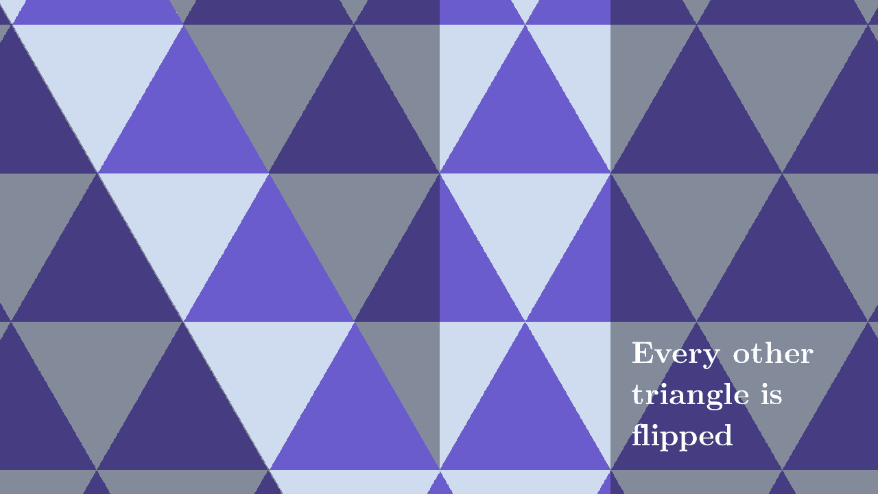
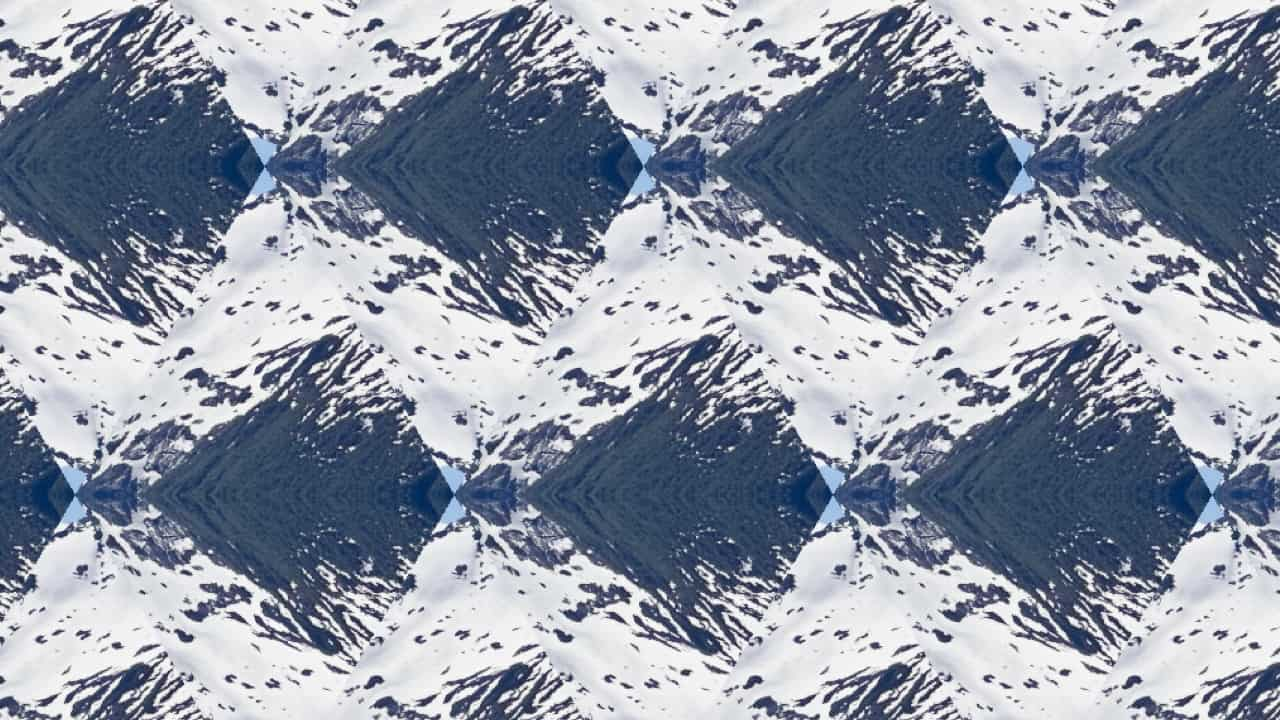
At this point, all that is left to make a triangular tiling is to split the rhombi in half by introducing vertical lines. You see the result in the figure below. Here, every other triangle is colored with a light / dark color.

Making a coordinate system of the tiled triangles
This section is a tangent, feel free to skip.
Before moving forward with recreating the triangle kaleidoscope pattern, it is important to consider how to describe the position of each triangle.
The tiling of rhombi is made from two rotated horizonal lines—stripeIndexLeft and stripeIndexRight. This means two parameters are used to describe each rhombus. A rhombus can therefore be named by a 2-tuple—say (stripeIndexLeft, stripeIndexRight).
When the origin is the center rhombus, the following coordinate system emerges:
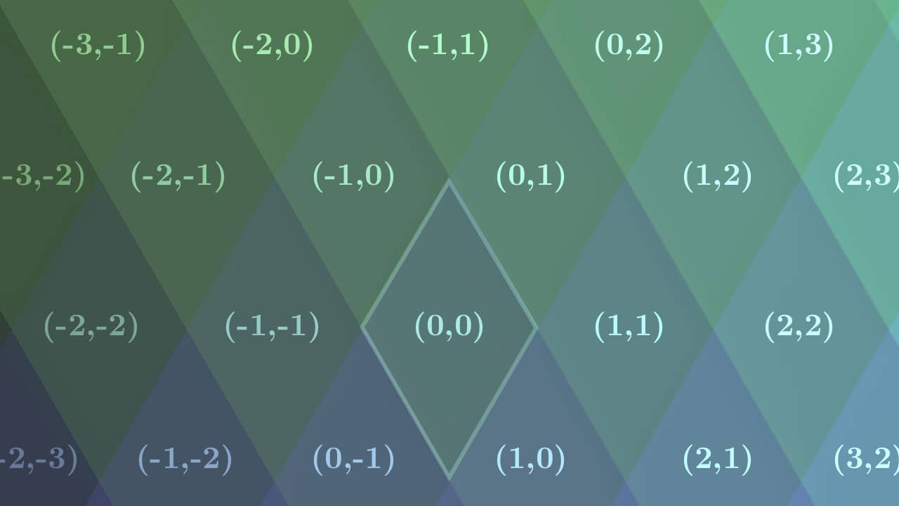
The coordinates might seem counterintuitive at first, but are in fact just a result of the line rotation. Some interesting observations are:
- Rhombi directly to the right/left of each other have both the first and second coordinate increased/decreased by 1.
- Rhombi directly above/below each other also have the first and second coordinate increased/decreased by 1.
When the vertical lines are introduced to make triangles, each triangle can be named by a 3-tuple. If the vertical lines are called stripeIndexVert, (stripeIndexLeft, stripeIndexRight, stripeIndexVert) can give the position of a triangle. For example:
- The rhombus at (0, 0) will contain two triangles with coordinates (0, 0, 0) and (0, 0, 1)
- The rhombus at (0, 1) will have two triangles with coordinates (0, 1, -1) and (0, 1, 0).
Making the center triangle the origin
It is desirable to have the center triangle/rhombus be the origin. This can be achieved by offsetting the indices by half the total number of lines. This means the total number of lines has to be known.
When no rotation is made, the number of lines can be found by dividing the size of the dimension by the width of each line. For instance, finding the number of vertical lines is done by dividing the total height by the height of each line:
$$ \text{numVerticalStripes} = {\text{height} \over \text{lineHeight}} $$
When an object is rotated, its bounded size increases. You can see this in the figure, where the extent of the rotated square is greater than the dimensions of the square itself.

This means the total area the lines cover is greater, and hence there are more lines when they are rotated. The bounded size of a rotated object can be modeled according to the following formula:
$$ \text{rotatedWidth} = \text{width} * \cos(\text{thetaAcute}) \\ + \text{height} * \sin(\text{thetaAcute}) $$
$$ \text{rotatedHeight} = \text{height} * \cos(\text{thetaAcute}) + \text{width} * \sin(\text{thetaAcute}) $$
which simplifies to
$$ \text{rotatedBounds} = \begin{bmatrix} \cos(\text{thetaAcute}) && \sin(\text{thetaAcute}) \\ \sin(\text{thetaAcute}) && \cos(\text{thetaAcute}) \end{bmatrix} \cdot \begin{bmatrix} \text{width} \\ \text{height} \end{bmatrix} $$
The number of left and right stripes can thus be found by dividing the rotated width by the triangle height.
$$ \text{numLeftStripes} = \text{numRightStripes} = {\text{rotatedWidth} \over \text{triHeight}} $$
Some key observations are:
- The rotated width is used for both left and right stripes since these lines would have been horizontal if not rotated
- The width of these lines equal the height of the tiled triangles.
- The number of left and right stripes are the same since they are rotated by the same acute angle and they have the same width.
The indicies can be offset by half the number of left/right stripes to make the center triangle have position (0, 0).
Immitating the triangle kaleidoscope pattern
The pattern in a triangle kaleidoscope is made from reflections in mirrors. This effect can however be recreated by copying regions of the image and rotating them.
For simplicity, the center triangle is chosen to be reflected. This means the region around the center triangle is the one to be copied and reflected.
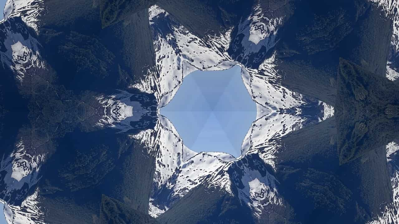
Investigating the pattern from a triangle kaleidoscope
To get a picture of how to rotate and copy the center triangle, one may look at an image that has been through a triangle kaleidoscope. The below figure is a result of orange and white horizontal lines in a triangle kaleidoscope.

The properties to notice are:
- The center triangle remains unchanged, or rotated by 0°
- There is a repeating hexagonal pattern from the center triangle being rotated 60°, 120°, 180°, 240° and 300°.

If you look at the rhombi, each containing two triangles, you might be attentive of another important observation. The bottom triangle in every rhombus is a vertically flipped copy of the top triangle. This makes it so that all triangles with the same left and right stripe index should be rotated by the same amount, and the flipped triangles should just mirror vertically the top triangles.
The roatation angles are found from the top-triangles and are thus: 0°, 120° and 240°. Then:
- The 60° triangle is a vertical mirror of the 120° triangle.
- The 180° triangle is a vertical mirror of the 0° triangle.
- The 300° triangle is a vertical mirror of the 240° triangle.

On the CPU, this property can be exploited to make half the number of image-rotations.
By rotating the top triangles first and then copying these with a vertical flip will produce the same image with less rotation-operations.
Figuring out which triangles are flipped
In order to vertically mirror, one must have a way of determining if a triangle is flipped. You might have noticed that every other triangle in a rotated stripe is flipped, similarly every other triangle vertically is flipped.
This leaves the following condition:
- If the stripeIndexLeft is odd, or stripeIndexRight is odd, but not both
- Then: Triangle is flipped if on an even row.
- Otherwise: Triangle is flipped if on an odd row.
The condition that stripeIndexLeft, or stripeIndexRight is odd, but not both is an exclusive-OR (XOR). Since one of these needs to be odd, but not both, the same result is given if the sum of stripeIndexLeft and stripeIndexRight is tested to be odd.
This is because only an even number added with an odd number will result in an odd number. It is beyond the scope of this article to prove this. In short:
- Even + Even = Even
- Odd + Odd = Even
- Even + Odd = Odd
Hence:
$$ (2 \nmid \text{stripeIndexLeft}) \oplus (2 \nmid \text{stripeIndexRight}) = 2 \nmid (\text{stripeIndexLeft} + \text{stripeIndexRight}) $$
∤ is the symbol for “Does not divide”, and ⊕ is the symbol for XOR.
The following code will determine if a triangle if flipped or not. Here, the floating point modulus function is used to test if a number is odd. The absolute value is taken because fmod forwards the negative sign.
half index = stripeIndexRight + stripeIndexLeft;

bool isOddRow = (int)fmod(abs(stripeIndexVert), 2.0h) == 0;
bool isFlipped = isOddRow
    ? (int)fmod(abs(index), 2.0h) == 0
    : (int)fmod(abs(index), 2.0h) == 1;
Copying the center triangle
The next step is to copy the center triangle to the other triangles. In order to figure out which pixel in the center triangle to copy, the program needs to know the position of the current triangle. One way of achieving this is to calculate the relative distance from the current triangle to the center triangle.
Since each triangle is described by three indices, these could be used to calculate the relative distance from the center triangle. Looking at the indices that describe each triangle gives the following table:
| Left Stripe Index | Right Stripe Index | Vertical Stripe Index | Distance From Center Tri |
|---|---|---|---|
| 0 | 0 | 0 | (0, 0) |
| 0 | 0 | 1 | (0, 1) |
| -1 | 0 | 0 | (-1, 0) |
| -1 | 0 | -1 | (-1, -1) |
| 0 | 1 | 0 | (1, 0) |
| 0 | 1 | -1 | (1, -1) |
| 1 | 1 | 0 | (2, 0) |
| -1 | 1 | -1 | (0, -1) |
The units for the distance is half the triangle size for the x-distance, and the triangle height for the y-distance.

From this table, the following observations could be made:
- The y-distance correlates exactly with the Vertical Stripe Index
- The x-distance is the sum of Left Stripe Index and Right Stripe Index
Thus:
$$ \Delta_x = \text{stripeIndexLeft} + \text{stripeIndexRight} $$
$$ \Delta_y = \text{stripeIndexVert} $$
With the units, the distance is found as follows:
$$ \text{distanceFromCenterTri} = \begin{bmatrix} \text{stripeIndexLeft} + \text{stripeIndexRight} \\ \text{stripeIndexVert} \end{bmatrix} \cdot \begin{bmatrix} \text{triSize} \over 2 \\ \text{triHeight} \end{bmatrix} $$
This makes it possible to find the position of the current triangle by offsetting the position of the center triangle with the found distance:
$$ \text{currentTrianglePosition} = \text{centerTrianglePosition} + \text{distanceFromCenterTri} $$
Resulting in the following code:
half2 centerTrianglePosition = offset - triangleSize_2;

half2 normDistanceFromCenterTri = half2(stripeIndexLeft + stripeIndexRight, stripeIndexVertCenter);
half2 distanceFromCenterTri = normDistanceFromCenterTri * half2(triangleSize_2.x, triangleSize.y);

half2 currentTrianglePosition = centerTrianglePosition + trianglePositionCenterOffset;

ushort2 currentCoordInCenterTriangle = translatedCoordinate((half2)hGid, currentTrianglePosition, centerTrianglePosition);

float4 color = textureIn.read(currentCoordInCenterTriangle);
textureOut.write(color, gid);
Where translatedCoordinate is defined like so:
ushort2 translatedCoordinate(half2 hGid, half2 positionInSquare, half2 targetPosition) {
    half2 hDirection = hGid - positionInSquare;
    half2 hCoord = targetPosition + hDirection;
    return ushort2(hCoord);
}
Producing this image:
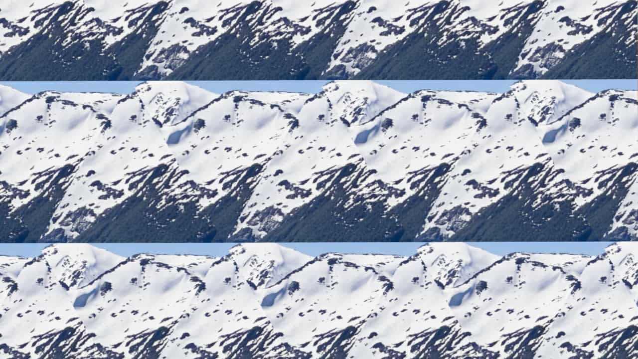
Recall that flipped triangles should be vertical mirrors of the above triangle. This can be implemented as follows:
if (isFlipped) {
    centerTrianglePosition.y += hTriHeight_2;
    currentCoordInCenterTriangle = verticallyReflectedCoordinate(currentCoordInCenterTriangle, centerTrianglePosition);
}
Where verticallyReflectedCoordinate executes the following:
ushort2 verticallyReflectedCoordinate(ushort2 gid, half2 offset) {
    unsigned short sectionStartY = (ushort)offset.y;
    unsigned short directionY = gid.y - sectionStartY;
    ushort2 coord = ushort2(gid.x, sectionStartY - directionY);

    return coord;
}
Producing the following image:
Figuring out what angle to rotate each triangle by
The last key in order to recreate the triangluar kaleidoscope pattern is the angle to rotate the copied region by. This can also be found from the stripeIndexLeft and stripeIndexRight.
As found in the investigation of the pattern above, the possible angles are 0°, 120° and 240°. These can be factored into an integer multiple of the base angle of 120°. This integer multiple will be refered to as the angle index. So:
$$ \begin{bmatrix} 0° \\ 120° \\ 240° \end{bmatrix} = \begin{bmatrix} 0 \\ 1 \\ 2 \end{bmatrix} \cdot 120° $$
In the triangle kaleidoscope, you may notice that the angles keep repeating, starting at a different angle for each stripe:
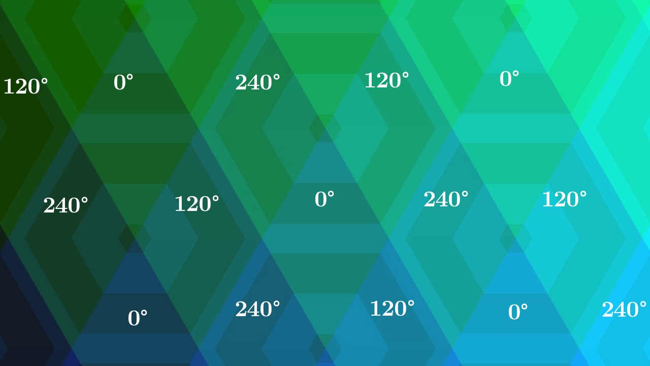
This behaviour can be modeled by taking one of the indices as a “pivot” and using the other index to offset from the pivot. The pivot is taken from the intersection between stripeIndexLeft and stripeIndexRight (i.e. when they are equal). Moving forward, stripeIndexRight is chosen arbitrarily to be used as the pivot index.
At the intersection between stripeIndexLeft and stripeIndexRight, the angles are:
| Left/Right Stripe Index | Angle | Angle Index |
|---|---|---|
| -2 | 120° | 1 |
| -1 | 240° | 2 |
| 0 | 0° | 0 |
| 1 | 240° | 2 |
| 2 | 120° | 1 |
Looking only at the positive values, the angle index can be obtained like this:
$$ \text{angleIndex} = (2 * (\text{stripeIndexRight} \mod{3} )) \mod 3 $$
The inner-expression 2 * (stripeIndexRight mod 3) gives the repeating series: 0, 2, 4. Taking the modulus 3 of this series turns the last 4 into 1 and thus yields the angle index.
For negative stripeIndexRight values, these should be added to 3 such that -1 becomes 2 and -2 becomes 1. This is described by:
$$ \text{angleIndex} = \begin{cases} (2 * (\text{stripeIndexRight} \mod{3} )) \mod 3 , & \text{if } \text{stripeIndexRight} \geq 0 \\ \left(2 * \left(3 – (– \text{stripeIndexRight} \mod{3} )\right)\right) \mod 3 , & \text{otherwise} \end{cases} $$
And results in the function thetaPhaseIndexFromRightStripeIndex which gives the pivot for the angle index:
int thetaPhaseIndexFromRightStripeIndex(int index) {
    int size = 3;
    int phase = (int)fmod((half)index, (half)size);

    if (phase < 0) {
        phase = size + phase;
    }

    return (phase * 2) % 3;
}
Recall that
fmodignores the sign in the mod and forwards the negative sign.
In order to obtain the absolute angle index for any triangle every triangle should add an offset to the pivot. Notice that the angle indices down a stripe increases by one and wraps around at three.
Since the pivot gives the angle index when stripeIndexLeft and stripeIndexRight intersect, the offset here should be 0. Furthermore, moving down with the stripeIndexLeft should increase the index by one and wrap around at three. The offset can therefore be described by:
$$ \text{offset} = (\text{stripeIndexLeft} – \text{stripeIndexRight}) \mod 3 $$
When the offset is negative, similarly as with the pivot, the offset should be added to 3 such that -1 becomes 2 and -2 becomes 1.
Finding the angle to rotate by can thus be implemented like so:
int leftStripeThetaIndex = (int)fmod(stripeIndexLeft - stripeIndexRight, 3);
if (leftStripeThetaIndex < 0) {
    leftStripeThetaIndex = 3 + leftStripeThetaIndex;
}

int thetaIndex = (thetaPhaseIndexFromRightStripeIndex(stripeIndexRight) + leftStripeThetaIndex) % 3;
half thetaStep = M_2xPI_3;
half theta = (half)thetaIndex * thetaStep;
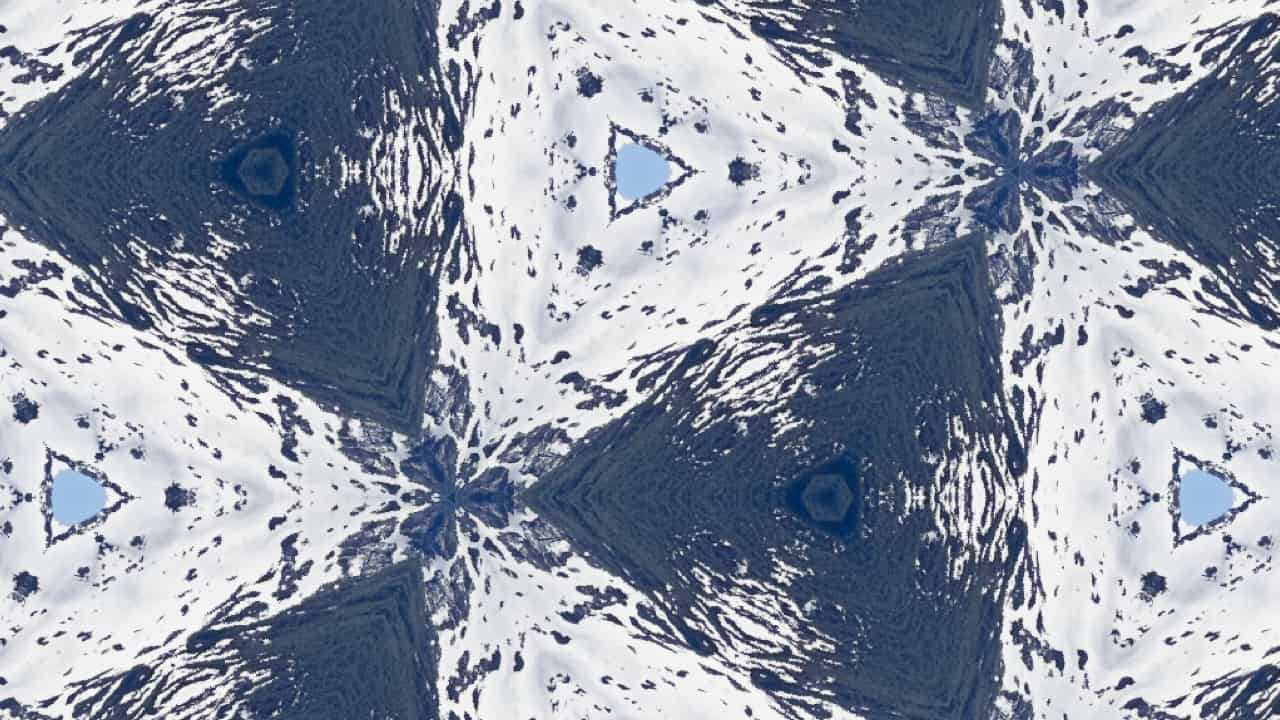
Which produces the following image, replicating the pattern of a triangle kaleidoscope.
Summary
Recreating the pattern of a triangle kaleidoscope has been an interesting challenge to solve on the GPU. While the process might be simpler to reason about on the CPU, investigating how to solve this on the GPU gives different perspective as one has to think in a slightly different way.
To sum up, the full process is as follows:
Make a grid of triangles: Divide the image into triangular regions by making three kinds of stripes—left stripes from rotating horizontal stripes 30° counterclockwise, right stripes by rotating horizontal stripes 30° clockwise, and vertical stripes. Each triangle is then described by three indices. Without the vertical stripes, the rotated stripes will form a grid of rhombi.
Copy the center triangle: Find the position of the current triangle from the relative distance between the current triangle to the center triangle. The distance to center can be found from the indices that describe each triangle. If a triangle is flipped, the copied center triangle should be vertically mirrored.
Rotate the copied triangle: The left stripe index and right stripe index can be used to find the angle to rotate by. The angles to rotate by follow a repeating pattern which can be recreated by having the intersection between the left and right stripe indices be the pivot / base angle and using the left stripe index as an offset from the intersection.
Some details—like making sure the grid of triangles has a triangle at the center of the image—have been left out for the sake of simplicity.
Other implementations to recreate the pattern of a triangle kaleidoscope exist. One example is Apple’s Core Image framework, which has a triangle kaleidoscope filter. The Core Image implementation also allows for rotating the triangle tiling and reducing the brightness the more the center triangle is mirrored (decay). Those are interesting features to recreate if moving forward with this graphics program.
You may find the final result of this article on GitHub2: Kaleidoscope.metal
Footnotes
1 [Reference] Metal Shading Language Specification 3.1 — 1.4 Metal and C++14
2 The full project can be found here: KaleidoscopeEngine.